Kettle Project : The Market Teardown History Aesthetics Process Concepts Costing Induction
For those of you engrossed in the kettle project's progress, there is some sad news. I have been whisked away to the big city of London for a work placement, and won't be messing up my mothers dining table with broken electronics for the foreseeable future.
My sincere apology comes in the form of a catch-up with where I was at the last point in the project.
My intention is at this point to develop a seamless kettle that uses electromagnetic induction to generate the heat from the base. This comes with a few specific problems:
1) In order to be unique from the idea of just putting a steel kettle on an existing induction hob, we must have some form of automatic, kettle-specific shutoff mechanism.
2) If the switchoff method is to be part of the main kettle body, some process must allow communication between the body and the base.
3) If this switchoff is to be seamless (the whole point of the idea), then how is it powered?
The above proposal solves and visually embodies these problems by containing within it seebeck Thermal Electronic Generators, which use the wasted heat from the kettle body to provide the small amount of power which must enable this wireless communication. Interestingly (after I proposed the solution) one of my favourite YouTubers, AvE, began a very similar project.
I got as far as having a TEG delivered, but not as far as testing. However, given the average journey of a kettle from 20-100 degrees in an environment of 20 degrees we can make a few calculations.
These are of little use to me as I'm sure the real effects will be massively different in the field, but in theory, with a little switching controller we can charge a batttery for low energy transmissions.
What I did do was have a proper look at the hardware.
The kettle arrived first, and at only £8 was quite a cheap and cool little kettle. Heating water was easy enough, and not incomparable to a standard electric kettle. A few major warning points are the fact that if left to boil, quite serious problems could occur, and the whistle is both annoying and inaudible to certain people (something Richard Sapper attempted to solve).
The hob came second, and at only £30, it means we have got our cool little induction kettle for a mere £38! One problem though, it's massive!
Why? Well unfortunately to find out, we're going to have to take it apart. What a shame!
Initial thoughts make me doubt it's need for a massive footprint. The induction ring itself is only about 200mm in diameter, and the fan was ineffective in the two minutes it took to boil the water. A pure induction kettle with no need for a full hour of cooking with a big pan wouldn't need to be this highly specified.
Having said that, there are some very beefy power components here, and a massive heatsink, so clever packaging and under-constraint might not solve all our problems.
A large dab of thermal paste at the center of the hob masks a very accurate temperature sensor, with which I was reliably able to keep the kettle at 80,100 and 120 degrees. Perhaps communication isn't totally necessary. Encouraging though to see this amount of tech available at £30 when you see how basic £30 kettles are.
The control and display board is a separate board and has room to be 'upgraded' into higher spec controls by the manufacturer. One word of advice, if you don't want an electric shock, don't connect it up to the power and press one of the springs!!
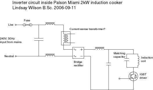
The heat sink covers the real workhorses of this product, a full bridge rectifier converts the AC into DC pulses, and the IGBT is the device which provides the variable power, by switching on and off the full power in the coil at a given percentage.
Now she's all apart, we can begin to work on exactly how she works.
I was surprised to see that the full power supply of the device is enabled not by heavy-gague wire, but merely by bigger than usual lines of solder on the underside of the main board. It gives us an an easy insight into the circuitry of the system though.
What we have is some very hefty (but low - Farad) capacitors regulating the voltage into a standard positive waveform, and the IGBT providing the required duty cycle for any given temperature or power level. We have a shutoff relay which makes sure power isn't instantly delivered on plug-in (or failure) and a bunch of miniature components and ICs which I assume are the brains which have been trained to deliver all these variable power levels and timings.
My final derived circuit diagram is, helpfully, very similar to another example of a circuit I found on another site.
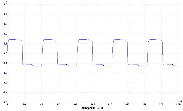
The source which also went beyond my capabilities in analysing the exact waveforms and duty-cycles involved in the heating process.
Voltage waveform on full boiling - 24kHz 46% duty cycle
So that's the technical respects of what we are dealing with. In conclusion, the induction technology is relatively easy to grasp at a basic level, although the size and specification of the large base are some definite issues which would need tackling in the future. Given my possession of a TEG, access to arduino and an ability to understand the switching, it would be a difficult but doable task to botch together a semi-functional working prototype. We'll have to see what time I have on my return to university.


No comments:
Post a Comment