Kettle Project : The Market Teardown History Aesthetics Process Concepts Costing Induction

In most projects, taking apart a product is a good way to think about what has come before, as well as reminding oneself about the tricky intricacies of real products in general. Here, it is even more important I'm looking to design an efficient, low cost and 'current' product.
So without further ado, let's get stuck in.
The Teardown

My teardown begins at the base, which has only one removable peice, the cover for the electronic connector. Notice how it only uses two screws, a solid connection would commonly require at least three, but here the other side of the connection has been cheaply snap fit.

And here the connector is, a Strix P69 connector, probably common to most fixed-position cordless kettles. It has a clever sprung door which is first dragged by the middle earth prong, exposing the live connectors.


And beides a few rubber feet, that's it for the base. In use, it tends to flail around a bit due to it's lightweight-ness under the influence of the stiff cord and the heavy kettle, but it's a very economical use of materials, with one complex piece doing all the jobs it can.


On to the main body of the kettle, our first priority is to remove the external screws and separate the two parts of plastic that make up the whole body.

This can be done by removing just four phillips screws, two at the top, and two at the base.

This separates the two main parts of the kettle. Lid & handle are connected, and the main controller is mounted onto the body.

The lid is mounted with rather shaky looking snap-fit joints which are very loose to movement. Also, given that they are composed of rather soft Polypropelene, I can't see them standing up to too many cycles of removal and re-attachment. Not that that is a priority.
Flipping the main body round, we can get to the brains of the machine.

And there it is, the Strix R7 controller. Released in 1985, the strix R-series has been the backbone of of most simple kettles for more than a generation. Strix currently have a 60% market share of the global kettle control market, and work with Beko, Braun, Bosch, Breville, DeLonghi, Kenwood... and nearly every other kettle brand you've heard of.

What's interesting is that this is literally the entire functional heart of the device. It connects directly to the switch, element and connector. You can also, for even further simplicity, connect it directly to a three-hole 'kettle plug', and do away with the base.

The switch is simply detached, and loosely houses the lamp and a sealed-in resistor.

Removing three screws is the last real job to do. The above screw was the third, and due to a small metal ring, and it's connection to the electronics, it was rather a lot harder to remove than the other three.

A large red sealing ring is exposed, and the element falls into the body.

The element and the controller connect in a very specific manner, the three screw holes going through the controller, and an assortment of connections, copper strips and pushrods form an interface.

The inside face of the element has a large copper strip and a small blob of thermal grease. My first assumption was that this strip was a bimetal that would be bending to thermally control the device.

And that's basically it as far as de-construction is concerned. In fact, for most practical industrial design purposes, this is as far as you need to go. Once these four (five if you include the switch) plastic pieces are specified according to the brand's needs, the only thing left is to source the element from outside, with the only requirement being that is is compatible with the famous Strix controller.
Clearly the plastic parts have constraints of their own, not least the correct fitting with the control components, but also they need to be produced in accordance with the right production processes.
Production Processes
The production process we are going to mainly consider is injection moulding. All of the 6 'designable' parts of this product have been injection moulded, and all of the 4 main parts are white Polypropylene. Polypropylene is the obvious choice for a kettle as it is very easy to mould, and fairly resistant (if a bit soft) in practical use. More importantly however, is ready available in food-safe variants.
Our investigation of injection moulding is going to develop by looking at the various main parts in increasing order of complexity. This isn't an explanation from the manufacturer, however, just my best guess at how it would be made. First, we look at the base, which is a very basic bit of moulding.

It is easy to work out how this has been moulded, and is in fact a perfect example of a simple two-plate mould. Helpfully, the join between the two moulds is both planar, and situated right at the bottom of the part, meaning an unsightly join line is avoided. One thing to note is the small bumps on the upper face. These are above the long holes on the underface (see earlier in this post), and are intended to avoid even more unsightly sink marks that would appear at these areas of complexity.

The lid seemed to me like another example of a simple two plate mould, but in fact there is a little ridge on the underside of the lip which goes against the main direction of split. This can be dealt with in some cases by a diagonal slide-out or ejection pin which facilitates this fairly necessary feature. Also note the ribs that circle the outer ridge, these reinforce the thin inner lip from shrinkage in the mould, and also are the main point of contact with the body when in position.
The next part, the handle, seemed at first glance to be another easy example of a two-part mould, but on further inspection, it's lower part had an array of features that were aligned perpendicular to the regular split direction.


The most complex part of the product however, unsurprisingly, is the main body.

What is semi-obvous is that the kettle tapers from top to bottom, which is a clear example of a macro- draft angle across the whole product, which helps with easy release from the mould, but is also a subtle influence on the aesthetics of the machine. Don't trust square sided plastic products!

This then gives us our general direction of split, but what troubled me the most was how the geometry of the handle , which clearly faces outward in completely the wrong direction. I attempted to map out my ideas spatially by using felt-tip to indicate the various parting lines and edges, but i was having trouble until some internet-sleuthing on alibaba led me to this image form a company producing moulds for water jugs.

Clearly this is very similar to the way the kettle is made too, with a bit of complexity. The final step was realising that the handle wasn't moulded by a part perpendicular to the main split, but as a product of both the top and bottom pieces.

Only a product of very high cost, or one produced in astronomical numbers can justify such a complex mould. I think we know which one this is, especially when it's cousins crop up on amazon -at three times the price I paid! ;)

So we have made a stab at how it's made, the next question is: how does it work? For that we have to investigate the electronics.
Electronic Control
The electronic control, as mentioned previously is exclusively how this kettle works. In order to investigate the exact details, we will have to have a look back at the R7 controller.

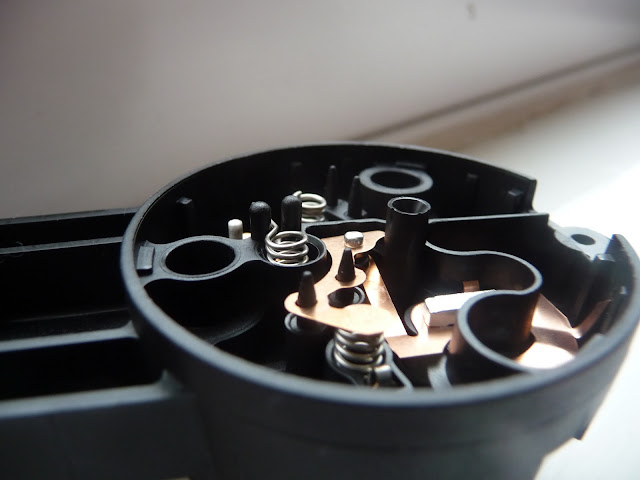
On the element-side of this device, there are three 'inputs'; at the top, a stripy bimetallic sensor, then, at the bottom, a white pushrod and a purply-colored bimetallic sensor.

From the side it is possible to see the relation between back and front, and also at the mechanism that connects the upper bimetal to the mechanical switch, and from there into the central body. The upper bimetal then, is clearly the sensor that ordinarily turns the kettle off when it is ready.


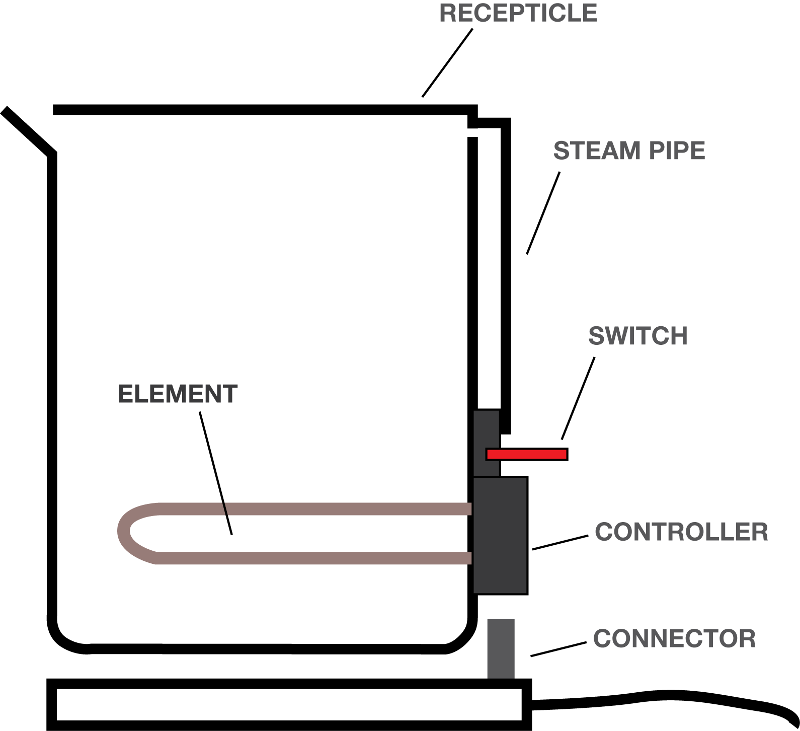
It does this by being exposed to hot steam which comes down from the top of the kettle via a 'steam pipe'. In more expensive kettles this is an actual pipe, but conveniently, here is just another peice of plastic. It is interesting that the rest of the device is not protected from steam ingress, as there is indirect contact with the steam from the kettle, although this must just be a symbol of the bimetal's consistency in detecting hot steam.


The other two devices we have to work out are the cutoffs. These work to prevent a dry-boil - where the kettle is turned on without water. They do this by turning the circuit off when the element gets unreasonably hot - a sure sign that the heat energy is not being passed on. From the outside, we can see the two pins which go into the controller to perform this action, and we know from the website and other sources that the controller actually has two cutoffs as extra security.


To investigate further, we are required to pop open the controller to see inside. The controller itself is made of just two pieces of injection moulded Polyamide (Nylon), and inside is an intricate network of flat, stamped copper pieces which are both the conductors and the switches of the internal circuit.
The location and working principle of the first cutoff (the one with the blue pushrod and the purple bimetal) is fairly clear.

The location and working principle of the first cutoff (the one with the blue pushrod and the purple bimetal) is fairly clear.


When the bimetallic sensor 'clicks' into position, the blue pushrod cuts the circuit. This is the case until the bimetal clicks back, which it does once it's cooled down. This is a safe practice that prevents the kettle melting itself, and helpfully, it does re-set, so we can use the kettle safely after a few minutes of our mistake.
The other cutoff is harder to work out. Especially as several bits of the circuit fell out upon opening it.


Here, 'cutoff 2' is linked by a spring to the circuit, this connection is also located in close proximity to the mechanical 'input' from the user's switch. When the controller is sandwiched between an 'on' switch and the element, this will always be closed. Which means what I assumed was a bimetallic strip (on the back of the element) has no use in breaking the circuit.
Doing some further testing, and finding Strix's own patent EP 0255347 B1, which described:
revealed the solution:
What we have is a three stage cutoff mechanism, each with a decreasing degree of 'forgiveness':

The first bimetal to snap is the usual steam sensor, which goes off once it meets steam at 100 degrees C, or thereabouts.
Failing that, or when boiling dry and the element overheats, the purple bimetal, 'cutoff 1' on the controller snaps and stops the circuit, and re-sets once it's cooled down, which can be done simply by re-immersing the element in water.
In a disaster situation where 'cutoff 1' has failed for some reason, the small yellowish pin will melt, where it has strategically been made very thin, this will release the spring and deactivate the circuit on the neutral side. This will irrecoverably damage the kettle, but at least your house is kept safe.

So there you go; that is, roughly, how a kettle works and is made. Now I have a decent understanding of what is is I am to design, the next stage is probably to get an understanding of what 'good design' means from a kettle's perspective, which may come in the next post in this series. Stay tuned!

The other cutoff is harder to work out. Especially as several bits of the circuit fell out upon opening it.

The bit of the circuit in question is that on the side of the neutral pin.

Doing some further testing, and finding Strix's own patent EP 0255347 B1, which described:
"A thermally-responsive control comprising a bimetal for initiating a control action in response to a predetermined over-temperature situation, a thermally collapsible element for initiating a control action in response to an extended overtemperature condition"
revealed the solution:
What we have is a three stage cutoff mechanism, each with a decreasing degree of 'forgiveness':

The first bimetal to snap is the usual steam sensor, which goes off once it meets steam at 100 degrees C, or thereabouts.
Failing that, or when boiling dry and the element overheats, the purple bimetal, 'cutoff 1' on the controller snaps and stops the circuit, and re-sets once it's cooled down, which can be done simply by re-immersing the element in water.
In a disaster situation where 'cutoff 1' has failed for some reason, the small yellowish pin will melt, where it has strategically been made very thin, this will release the spring and deactivate the circuit on the neutral side. This will irrecoverably damage the kettle, but at least your house is kept safe.

So there you go; that is, roughly, how a kettle works and is made. Now I have a decent understanding of what is is I am to design, the next stage is probably to get an understanding of what 'good design' means from a kettle's perspective, which may come in the next post in this series. Stay tuned!
An excellent explanation and an better than anything I've found searching the web. Thank you so much for taking the time to document and share with viewers. Very informative and much appreciated!
ReplyDeleteMack L.
Where can I found the electronic control as a spare part?
ReplyDeleteA market teardown involves analyzing the competition and identifying opportunities for growth. In the context of online logo design services in UK and USA, this would mean researching the logos of other video animation companies and looking for ways to differentiate your own logo from theirs. It's important to make sure that your logo stands out and represents your unique brand identity.
Deleteexcelente trabajo
ReplyDeleteHi I'm an industrial design student currently doing a kettle redesign. I was wondering if the second cut off spring (the piece of extra metal coming off it) should be under the copper piece? Since when the plastic piece melts the spring will release breaking the circuit.
ReplyDeleteYep you could be right! These things are difficult to put together once taken apart! good spot :)
DeleteAmazingly detailed and helpful. I wondered the same thing as Tom Ratlidge about the second cut off spring too. I fixed this one (dismantled, cleaned with isopropyl alcohol etc) but the contacts at cut-off 2 quickly got scorch marks on them, and the switch stopped working. I am trying to ascertain why. The two white pins are very similar, but one is slightly longer than the other (by about 3 mm) and I may have put them back the wrong way around. Having said that it did work when I re-assembled it yesterday, but stopped working today, which is when I noticed the scorch marks. Maybe the pin at cut-off 2 could benefit from WD-40. Hard to tell. Also I don't understand why it has taken over 10 years for the switch to fail. Hard to find a replacement R7 online, hence trying to repair this one (and save the planet by not throwing away my Kenwood JK630 kettle!). Thanks for the explanations above. Very useful!
ReplyDeleteUpdating the above, my issue isn't the white pins: the longer one must be at "cut off 2" as the shorter one doesn't reach the rocker switch.
ReplyDeleteA (non-STRIX) spare is available from various AliExpress sellers, I have seen. Just ordered one for £3.24 (delivered) to UK. I can at least swap the disk - I think my steam disk is slightly rusty and doesn't spring quickly enough, thus causing arcing in the control itself.... that's my theory currently, anyway!
ReplyDeleteGood stuff! Let me know how it goes. Tells you the state of things when you can get a new kettle for £5 but it’s so hard to get hold of bits!
DeleteI had to clean mineral deposit off of the white pin and white pin tube/holder by pushing some cotton-swab cotton soaked in vinegar through the hole with a needle. Then some wd40 into the white-pin tunnel and it's working more stable now instead of intermittent.
DeleteThe white-pin cut-off works by directing steam towards the top bimetal but reaches further over time. If only distilled water would be boiled I don't think the white pin could get stuck.
This is my third attempt to comment. This blog doesn't seem to like me. I wanted to thank Tom for the useful information and to Runaway for sharing his experience. However, I have been having difficulty finding the replacement part on Aliexpress. Is it possible to post a link or give me a search phrase that works?
ReplyDeleteHello. For the second cut-off connection, I misplaced the white pushrod. What can I use as an alternative or where can I get an exact replica for replacement?
ReplyDelete